Product Parameters:
1. Machine Overview
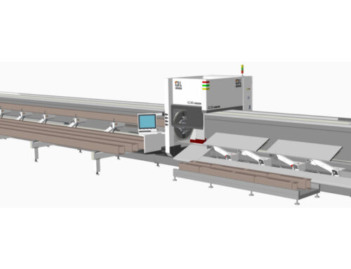
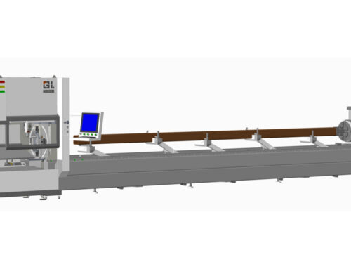
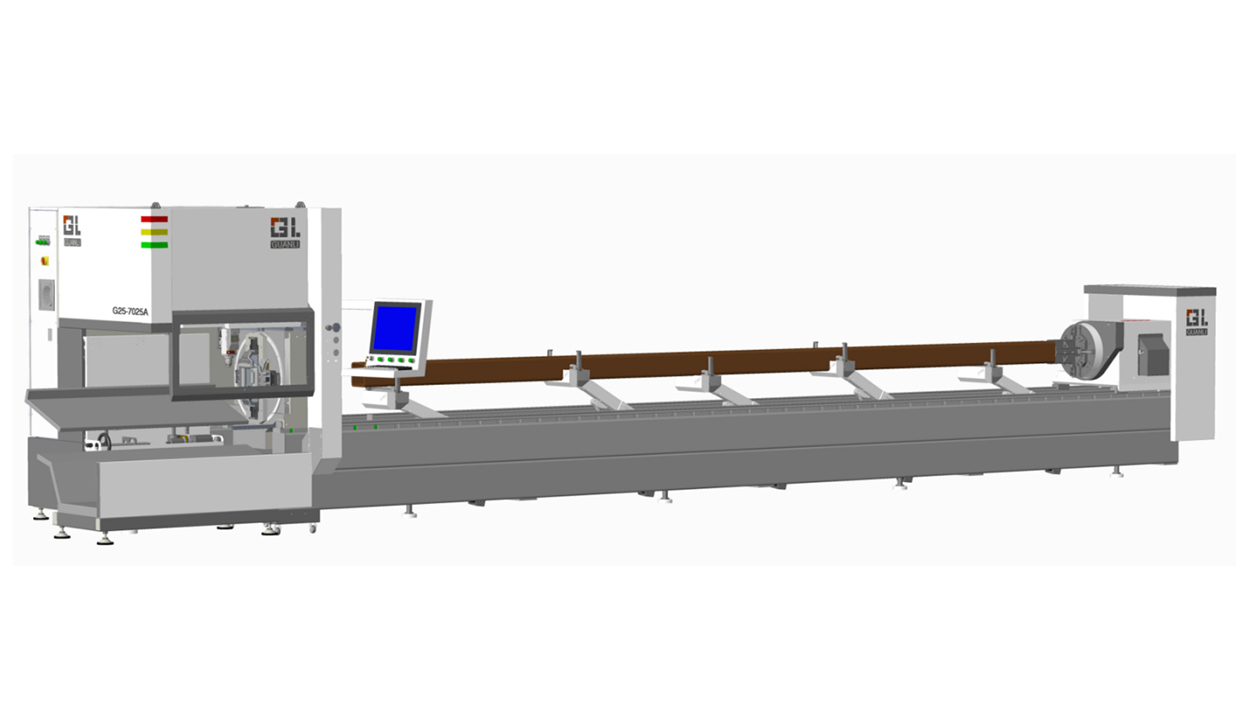
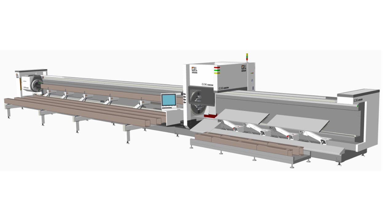
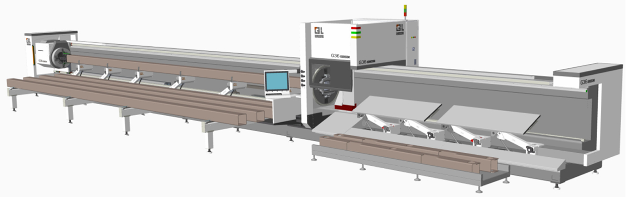
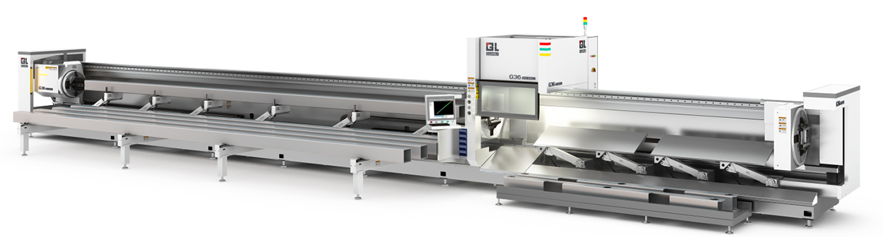
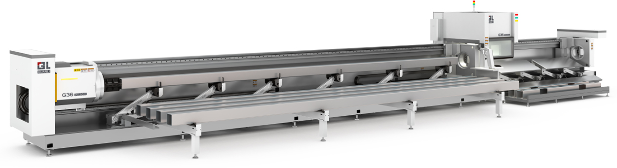
The 12036B extends the G36 family to a 12-meter platform — the extra-long configuration for fabrication that processes full-length structural tube and wants to cut it in the fewest setups. Power and motion hardware follow the series: 6,000 W source, 80 rpm / 0.8 G chuck, two-chuck motor avoidance with 20–45 mm tail waste, cross-mounted dust-proof guide rails and the welded, annealed bed with side-hung cutting structure.
2. Key Advantages
- 12 m extra-long platform — full-length bars with minimal re-positioning.
- 6,000 W source — carbon steel to 30 mm, stainless to 25 mm, aluminum to 25 mm.
- Φ20–360 mm tube range on one machine.
- Five-tube continuous loading, 45–55 s cycle.
- 20–45 mm tail waste via two-chuck motor avoidance.
3. Welded, Stress-Relieved Machine Bed
Welded plate-and-tube construction, stress-relieved in a 600 °C anneal held 4.5 hours and furnace-cooled, then rough-machined and finish-machined. At 12 meters, the stabilized bed is the difference between a machine that holds tolerance along its whole length and one that twists under its own weld stress.
4. Automatic Loading on the Side-Hung Structure
The side-hung (cantilever) cutting structure is integrated with the automatic loading machine. The semi-automatic loader carries five tubes and feeds them continuously on a 45–55 s cycle — the slightly longer cycle of the extra-long platform.
5. Cutting Performance
Published 6,000 W process parameters (speeds in m/min; for 1–4 mm carbon steel the first figure is oxygen and the second air; oxygen is marked from 14 mm on the source chart):
Aluminum assist gas is not tagged on the source 6,000 W chart (nitrogen shown per the 3,000 W data). Dual carbon-steel speeds = oxygen / air; oxygen from 14 mm. Full range: carbon steel 1–30 mm, stainless 1–25 mm, aluminum 1–25 mm, brass 1–16 mm, copper 1–12 mm.
| Material | Thickness (mm) | Cutting Speed (m/min) | Assist Gas |
|---|---|---|---|
| Carbon steel Q235 | 1 | 8.0–12 / 35–50 | Oxygen |
| Carbon steel Q235 | 3 | 3.5–5.0 / 15–20 | Oxygen |
| Carbon steel Q235 | 6 | 2.6–3.2 | Oxygen |
| Carbon steel Q235 | 10 | 2.0–2.6 | Oxygen |
| Carbon steel Q235 | 20 | 0.7–0.9 | Oxygen |
| Carbon steel Q235 | 30 | 0.15–0.2 | Oxygen |
| Stainless steel 304 | 1 | 35–60 | Nitrogen |
| Stainless steel 304 | 3 | 15–19 | Nitrogen |
| Stainless steel 304 | 6 | 5.0–8.0 | Nitrogen |
| Stainless steel 304 | 10 | 2.3–3.0 | Nitrogen |
| Stainless steel 304 | 20 | 0.2–0.3 | Nitrogen |
| Stainless steel 304 | 25 | 0.15–0.2 | Nitrogen |
| Aluminum alloy | 1 | 35–60 | Nitrogen |
| Aluminum alloy | 3 | 12–18 | Nitrogen |
| Aluminum alloy | 6 | 4–5.5 | Nitrogen |
| Aluminum alloy | 10 | 1.5–2.3 | Nitrogen |
| Aluminum alloy | 16 | 0.5–0.8 | Nitrogen |
| Aluminum alloy | 25 | 0.12–0.2 | Nitrogen |
| Brass | 1 | 30–60 | Nitrogen |
| Brass | 3 | 15–18 | Nitrogen |
| Brass | 6 | 4.2–5.5 | Nitrogen |
| Brass | 10 | 1–1.6 | Nitrogen |
| Brass | 16 | 0.5–0.7 | Nitrogen |
| Copper | 1 | 30–60 | Oxygen |
| Copper | 3 | 12–15 | Oxygen |
| Copper | 6 | 2.5–4.5 | Oxygen |
| Copper | 10 | 0.7–1.2 | Oxygen |
6. Power, Cooling and Gas Supply
Gas supply pressures: nitrogen ≥ 2.0 MPa; compressed air ≥ 1.3 MPa with flow ≥ 2.5 m³/min; oxygen ≥ 1.0 MPa.
| Item | Requirement |
|---|---|
| Power supply | Three-phase five-wire 380–400 VAC, 50 Hz; recommended capacity ≥ 60 kVA, voltage stability ± 2%, grounding resistance ≤ 3 Ω |
| Cooling water | 40 L distilled / deionized water, conductivity < 10 µS/cm |
| Assist gas | Oxygen purity ≥ 99.6%; nitrogen purity ≥ 99.99%; supply pressures: N₂ ≥ 2.0 MPa, air ≥ 1.3 MPa (≥ 2.5 m³/min), O₂ ≥ 1.0 MPa |